mirror of
https://github.com/netbox-community/netbox.git
synced 2026-04-15 05:29:54 +02:00
Add support for spliced pigtails / punched cable to rear ports #2334
Closed
opened 2025-12-29 17:24:55 +01:00 by adam
·
10 comments
No Branch/Tag Specified
main
21866-sql
post-raw-signal
feature
21782-config
21361-tests
21157-export-template-public-models
21025-pre-render-config-contexts
21364-swagger
feature-ip-prefix-link
20911-dropdown-3
fix_module_substitution
21160-filterset
20911-dropdown-2
20044-elevation-stuck-lightmode
7604-filter-modifiers-v3
20660-script-load
19724-graphql
14884-script
19720-macaddress-interface-generic-relation
fix-19669-api-image-download
7604-filter-modifiers
19275-fixes-interface-bulk-edit
fix-17794-get_field_value_return_list
11507-show-aggregate-and-rir-on-api
9583-add_column_specific_search_field_to_tables
v4.6.0-beta1
v4.5.8
v4.5.7
v4.5.6
v4.5.5
v4.5.4
v4.5.3
v4.5.2
v4.5.1
v4.5.0
v4.4.10
v4.4.9
v4.5.0-beta1
v4.4.8
v4.4.7
v4.4.6
v4.4.5
v4.4.4
v4.4.3
v4.4.2
v4.4.1
v4.4.0
v4.3.7
v4.4.0-beta1
v4.3.6
v4.3.5
v4.3.4
v4.3.3
v4.3.2
v4.3.1
v4.3.0
v4.2.9
v4.3.0-beta2
v4.2.8
v4.3.0-beta1
v4.2.7
v4.2.6
v4.2.5
v4.2.4
v4.2.3
v4.2.2
v4.2.1
v4.2.0
v4.1.11
v4.1.10
v4.1.9
v4.1.8
v4.2-beta1
v4.1.7
v4.1.6
v4.1.5
v4.1.4
v4.1.3
v4.1.2
v4.1.1
v4.1.0
v4.0.11
v4.0.10
v4.0.9
v4.1-beta1
v4.0.8
v4.0.7
v4.0.6
v4.0.5
v4.0.3
v4.0.2
v4.0.1
v4.0.0
v3.7.8
v3.7.7
v4.0-beta2
v3.7.6
v3.7.5
v4.0-beta1
v3.7.4
v3.7.3
v3.7.2
v3.7.1
v3.7.0
v3.6.9
v3.6.8
v3.6.7
v3.7-beta1
v3.6.6
v3.6.5
v3.6.4
v3.6.3
v3.6.2
v3.6.1
v3.6.0
v3.5.9
v3.6-beta2
v3.5.8
v3.6-beta1
v3.5.7
v3.5.6
v3.5.5
v3.5.4
v3.5.3
v3.5.2
v3.5.1
v3.5.0
v3.4.10
v3.4.9
v3.5-beta2
v3.4.8
v3.5-beta1
v3.4.7
v3.4.6
v3.4.5
v3.4.4
v3.4.3
v3.4.2
v3.4.1
v3.4.0
v3.3.10
v3.3.9
v3.4-beta1
v3.3.8
v3.3.7
v3.3.6
v3.3.5
v3.3.4
v3.3.3
v3.3.2
v3.3.1
v3.3.0
v3.2.9
v3.2.8
v3.3-beta2
v3.2.7
v3.3-beta1
v3.2.6
v3.2.5
v3.2.4
v3.2.3
v3.2.2
v3.2.1
v3.2.0
v3.1.11
v3.1.10
v3.2-beta2
v3.1.9
v3.2-beta1
v3.1.8
v3.1.7
v3.1.6
v3.1.5
v3.1.4
v3.1.3
v3.1.2
v3.1.1
v3.1.0
v3.0.12
v3.0.11
v3.0.10
v3.1-beta1
v3.0.9
v3.0.8
v3.0.7
v3.0.6
v3.0.5
v3.0.4
v3.0.3
v3.0.2
v3.0.1
v3.0.0
v2.11.12
v3.0-beta2
v2.11.11
v2.11.10
v3.0-beta1
v2.11.9
v2.11.8
v2.11.7
v2.11.6
v2.11.5
v2.11.4
v2.11.3
v2.11.2
v2.11.1
v2.11.0
v2.10.10
v2.10.9
v2.11-beta1
v2.10.8
v2.10.7
v2.10.6
v2.10.5
v2.10.4
v2.10.3
v2.10.2
v2.10.1
v2.10.0
v2.9.11
v2.10-beta2
v2.9.10
v2.10-beta1
v2.9.9
v2.9.8
v2.9.7
v2.9.6
v2.9.5
v2.9.4
v2.9.3
v2.9.2
v2.9.1
v2.9.0
v2.9-beta2
v2.8.9
v2.9-beta1
v2.8.8
v2.8.7
v2.8.6
v2.8.5
v2.8.4
v2.8.3
v2.8.2
v2.8.1
v2.8.0
v2.7.12
v2.7.11
v2.7.10
v2.7.9
v2.7.8
v2.7.7
v2.7.6
v2.7.5
v2.7.4
v2.7.3
v2.7.2
v2.7.1
v2.7.0
v2.6.12
v2.6.11
v2.6.10
v2.6.9
v2.7-beta1
Solcon-2020-01-06
v2.6.8
v2.6.7
v2.6.6
v2.6.5
v2.6.4
v2.6.3
v2.6.2
v2.6.1
v2.6.0
v2.5.13
v2.5.12
v2.6-beta1
v2.5.11
v2.5.10
v2.5.9
v2.5.8
v2.5.7
v2.5.6
v2.5.5
v2.5.4
v2.5.3
v2.5.2
v2.5.1
v2.5.0
v2.4.9
v2.5-beta2
v2.4.8
v2.5-beta1
v2.4.7
v2.4.6
v2.4.5
v2.4.4
v2.4.3
v2.4.2
v2.4.1
v2.4.0
v2.3.7
v2.4-beta1
v2.3.6
v2.3.5
v2.3.4
v2.3.3
v2.3.2
v2.3.1
v2.3.0
v2.2.10
v2.3-beta2
v2.2.9
v2.3-beta1
v2.2.8
v2.2.7
v2.2.6
v2.2.5
v2.2.4
v2.2.3
v2.2.2
v2.2.1
v2.2.0
v2.1.6
v2.2-beta2
v2.1.5
v2.2-beta1
v2.1.4
v2.1.3
v2.1.2
v2.1.1
v2.1.0
v2.0.10
v2.1-beta1
v2.0.9
v2.0.8
v2.0.7
v2.0.6
v2.0.5
v2.0.4
v2.0.3
v2.0.2
v2.0.1
v2.0.0
v2.0-beta3
v1.9.6
v1.9.5
v2.0-beta2
v1.9.4-r1
v1.9.3
v2.0-beta1
v1.9.2
v1.9.1
v1.9.0-r1
v1.8.4
v1.8.3
v1.8.2
v1.8.1
v1.8.0
v1.7.3
v1.7.2-r1
v1.7.1
v1.7.0
v1.6.3
v1.6.2-r1
v1.6.1-r1
1.6.1
v1.6.0
v1.5.2
v1.5.1
v1.5.0
v1.4.2
v1.4.1
v1.4.0
v1.3.2
v1.3.1
v1.3.0
v1.2.2
v1.2.1
v1.2.0
v1.1.0
v1.0.7-r1
v1.0.7
v1.0.6
v1.0.5
v1.0.4
v1.0.3-r1
v1.0.3
1.0.0
Labels
Clear labels
beta
breaking change
complexity: high
complexity: low
complexity: medium
needs milestone
netbox
pending closure
plugin candidate
pull-request
severity: high
severity: low
severity: medium
status: accepted
status: backlog
status: blocked
status: duplicate
status: needs owner
status: needs triage
status: revisions needed
status: under review
topic: GraphQL
topic: Internationalization
topic: OpenAPI
topic: UI/UX
topic: cabling
topic: event rules
topic: htmx navigation
topic: industrialization
topic: migrations
topic: plugins
topic: scripts
topic: templating
topic: testing
type: bug
type: deprecation
type: documentation
type: feature
type: housekeeping
type: translation
Mirrored from GitHub Pull Request
Milestone
No items
No Milestone
Projects
Clear projects
No project
Notifications
Due Date
No due date set.
Dependencies
No dependencies set.
Reference: starred/netbox#2334
Reference in New Issue
Block a user
Blocking a user prevents them from interacting with repositories, such as opening or commenting on pull requests or issues. Learn more about blocking a user.
Delete Branch "%!s()"
Deleting a branch is permanent. Although the deleted branch may continue to exist for a short time before it actually gets removed, it CANNOT be undone in most cases. Continue?
Originally created by @ktims on GitHub (Feb 1, 2019).
Environment
Proposed Functionality
Add support for patch panels that do not use connectors on the rear side.
Use Case
It is common for both fibre and copper patch panels to be 'hard wired' to another 'rear port' on another panel. Presently the model both enforces a connector on the rear port, and doesn't provide an appropriate connector type to model this.
Database Changes
I'm not sure the best nouns to use, but suggest the addition of two connector types to the cabling model, for 'pigtail fibre' and 'punched copper'. Perhaps just making the field nullable satisfies this, too, if connections to 'null' connectors are allowed. It should also be allowed to connector either of these types on one end to a connectorized panel on the other end.
@DanSheps commented on GitHub (Feb 1, 2019):
'punched copper' is still 8P8C
'pigtail fibre' is going to break out into individual strands with a individual connector (LC, SC, MPO, etc) (I always do color coded strands anyways, I never use the "position" for fiber)
@ktims commented on GitHub (Feb 1, 2019):
Punched copper isn't 8P8C if it doesn't have an 8P8C connector on it, which it doesn't if it's punched down on the rear of a patch panel.
The fibre does obviously break out to a connector, but that is what the front port is designed to model. On the rear I'd be happy to just have a '12 strand fibre' as a single connector, or break them out to individual strands, but currently you have to choose a connector type, which doesn't make sense when it's pigtails on both ends that are spliced into the patch panels.
You do bring up a good point though. If you model the individual strands (which I think is a good idea), it's also not reasonably possible to then actually connect these to an Interface, since most fibre Interfaces use two strands, but you're only allowed to connect one Front Port to each Interface. Modelling them as duplex pairs breaks down if you need to mix simplex and duplex links.
@DanSheps commented on GitHub (Feb 1, 2019):
Don't want to argue with you, but there is a 8P8C connector somewhere right? Just because the connector is on the front and you are punching down to the back doesn't make it any less of a 8P8C connector.
On a fiber panel, unless you are using the pigtail (I am assuming you actually mean MPO/MPT fan-out or MPO/MPT to LC/SC cassettes) changes are you are going into a housing to connect the two connectors together. You actually do have a connector on the both side (front and back), and if you really want to get down to it, you should be modelling these completely.
The other "other good point", I simply put a "Simplex/Duplex" converter object on my switches/interface modules and label them "Upstream/Downstream" (For example, TenGigabitEthernet1/1/1.Upstream and TenGigabitEthernet1/1/1.Downstream" and link the single interface to the LC connector with a "zero length" cable.
@ktims commented on GitHub (Feb 1, 2019):
The way Netbox models patch panels, there are two connectors for each circuit. One on the front, one on the rear. There is no physical connector on the rear (unless you count the IDC punch block as a connector... in which case it should appear in the list of options), therefore it doesn't make sense for the model to require one, which is the present state. Obviously the front port is 8P8C.
I don't know why you would assume such when I have clearly stated that's not what I'm talking about... this case is clearly supported. Let me reiterate the request is to add support for spliced pigtails.
This is a clumsy workaround. Better support would be appreciated.
@DanSheps commented on GitHub (Feb 4, 2019):
You don't need a new connector for spliced pigtails, as they will still either have a ST/SC/LC/etc connector.
@jeremystretch commented on GitHub (Feb 4, 2019):
8P8C is technically a modular form factor. We could add a "Fixed" type to represent punched-down terminations.
I'm not sure what you mean by "spliced pigtails." Can you share a photo?
You can model duplex and simplex links on the same device. For example, we have fiber ports named 1/2 and 3/4 for duplex links (two strands per port), and 5 and 6 for simplex links.
@ktims commented on GitHub (Feb 4, 2019):
Mea culpa. @DanSheps is right, I'd never actually closely examining the splice trays, but of course the pigtails terminate in connectors, for some reason I thought they were spliced directly to the bulkhead connectors. Sorry guys.
Hmm, I guess this works. It does tie the logical 'connection' a little closely to the physical plant for my liking (the modelling of the connectors / cables depends on what type of connection they are used for, not how the cable is built), but it's a decent compromise.
@DanSheps commented on GitHub (Feb 4, 2019):
Fixed or 110 would work. I mean, technically it is a 110 connection. I think everyone gets what is going on with 8P8C though, not everyone would get 110. Might get fixed, but might also mis-use it.
@jbakklund commented on GitHub (Feb 14, 2019):
Hi @jeremystretch. Here is a photo showing a patch panel delivered with factory mounted pigtails prepared for splicing incoming cable(s). This panel has 48 LC/APC connectors in front and no connectors at the rear other than the 48 naked fiber tails (or pigtails).
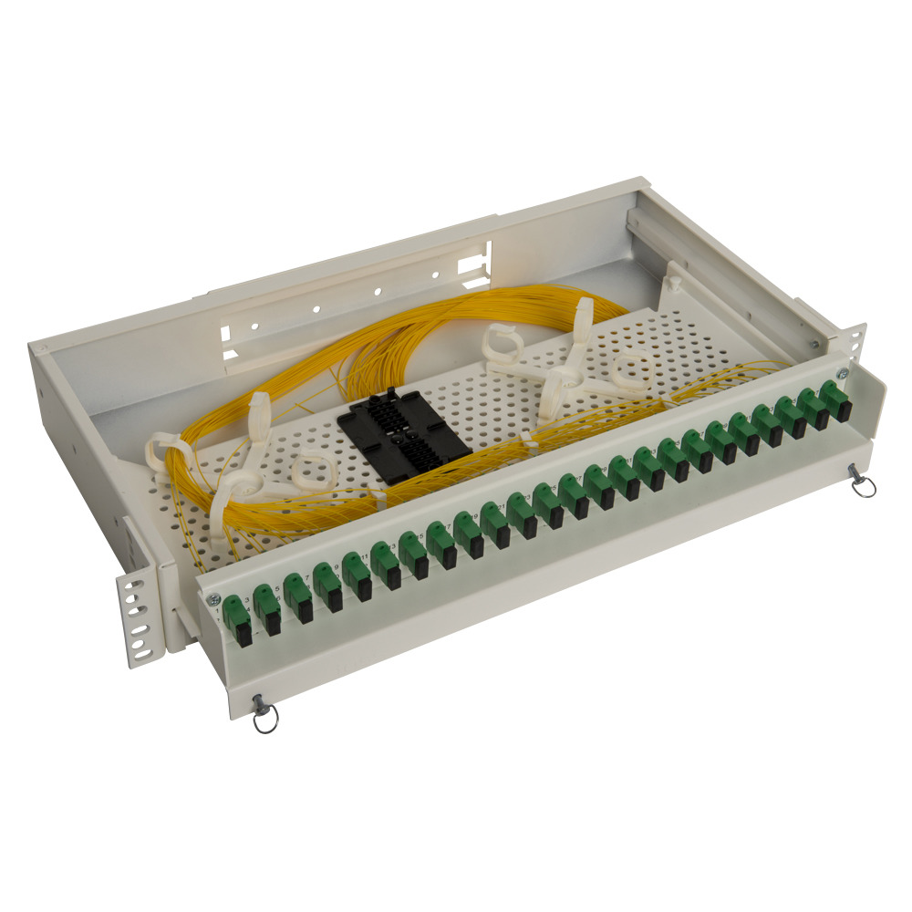
I have one such panel where 24 of the front ports (numbered 25-48) are related to one single rear 'port' named '25-48' of the fictitious type 'LC' with 24 positions (or fixed splices). They are all 'connected' to a 24-strand multicable connected to a rear port named '1-24' in the far end - and tracing a connection e.g. from port 29 at one end, via the fifth position at the rear to port 5 at the distant end - works just fine.
But allowing 'splice' or 'fixed splice' as connection type - would make sense in this case.
@DanSheps commented on GitHub (Feb 15, 2019):
@jbakklund what is the model of that cassette?